Our CAM Software Converts any DXF Drawings In G-Code
ServoMecanik ServoCAM Loading DXF or G-Code
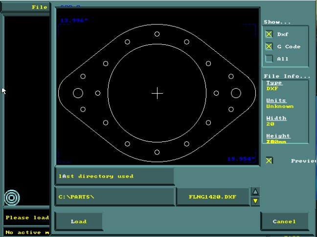
When the CAM Software ServoCAM loads first, the window allows you to view the shapes to download. The user can choose to view only DXF or G-code format files by checking the appropriate box. If the user selects “ALL” box, the will be able to view all DXF and G-code format files. The window also shows the approximate dimensions of the part. User can insert G-code files directly in a new nesting. Converted DXF parts in G-code with ServoCAM’s commands can be inserted into the same nesting as the G-code parts.
CAM Software | Loading DXF or G-Code files
ServoCAM Nesting, Plasma Laser CNC Cutter
ServoCAM | Nesting metric mixed with imperial
CAD users can choose to do all their programming from the desktop by converting DXF drawings to G-codes using ServoMecanik’s ServoCAM software. This CAM software, specifically developed by ServoMecanik, allows you to program, nest imperial and metric shapes together. The user can also upload any shape to the ServoTouch or any other motion control system. Our CAM software allows the user to define LEAD-IN, LEAD-OUT sizes and cutting order. It can also move, copy or delete any part on a already nested plate. With its intuitive and graphical environment, ServoCAM can be taught without any prior knowledge of CAD software, making it the smart choice for your drafting department.
Selection Imperial or Metric parts
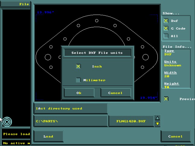
When selection of file to download is done, the user must determine the format of the units as imperial format or metric format. Take for example a piece whose dimensions are 100 x 120 unit, the piece could possibly be 100 in by 120 in or 100mm x 120mm. The part is loaded once the units is determined and will load into the ServoCAM environment. Dimensions will be truncated at 0.001 inch or 0.0254 mm allowing to maintain adequate and sufficient precision for plasma, laser or waterjet cutting.
Unit selection of parts in imperial or metric
Adjusttment of Lead In and Lead Out
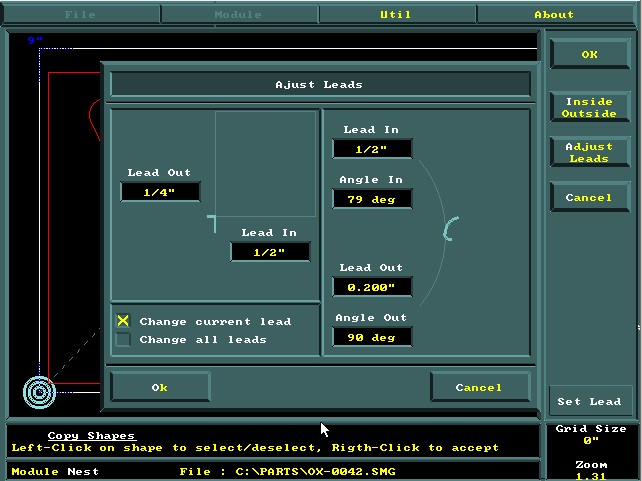
In this window appears the menu where the user sets the LEAD-IN and LEAD-OUT of the part. ServoCAM uses the values to encode the parts in G-code format. The LEAD-IN and LEAD-OUT can also adjust according to the dimensions of the holes and to the process to perform the cutting of the material. For example, if the parts to cuts are on a 2in thick steel plate using an Oxy-Fuel torch, the LEAD-IN should be at least 1in from the edge of the path of the cut in such a way that the splashes from the piercing does not deposit on the cutting path. While a 1/8-in thick steel plate, whose cutting process isdone with Plasma Power Source, the LEAD-IN can be at a distance of 1/4in from the cutting path leaving enough space so that the spatter cannot settle on the cutting path.
Configuration of Lead-in and Lead-out
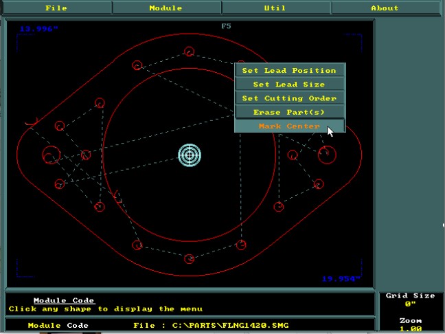
Select Lead-in ,Lead-out, cutting order
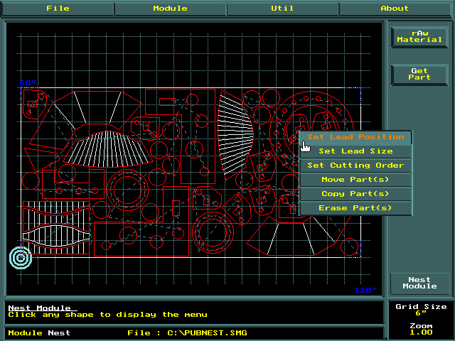
Once the part is G-code coded, the user can then reconfigure the size of the LEAD-IN and LEAD-OUT on a single hole or all the holes of the parts. The menu also allows you to select and erase a hole that does not need to be drilled or cut, saving the designer from redrawing the component. This command saves you time and makes changes directly on the production site in the blink of an eye. And finally, the user can also reset the cutting order in order to optimize the course of the cutting trajectory in order to minimize the deformation or the cutting time.
Select Lead-in ,Lead-out, cutting order
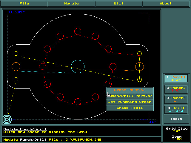
Drill, Punch, Cut on One Setup
ServoCAm let you Drill, Punch, Cut on One Setup
For those who have the ability to drill or punch with their CNC cutting machine, ServoCAM allows the programming of the puching and the drilling of the hole at the same time as the coding of the part cut. This option allows the user to save handling time. As you can see from the menu, ServoCAM also allows you to delete a hole and generate the cutting or drilling order. ServoCAM also gives you the option to select 4 different drilling or punching tools, which is usually more than enough to complete all the parts, saving the user from redoing a new setup on another machine.
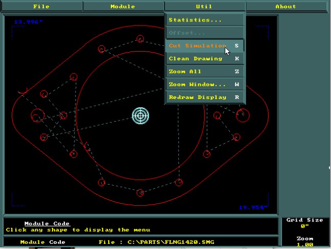
Run the Cutting Order Simulation
Once the part converted to G-code, the ServoCAM software allows the user to simulate the path of the cut. This command is very useful and confirms that all the holes are part of the cut path. The simulation command will provide a simulation of the cutting trajectory in a part or in a nesting . User will visualize the execution of the order of the parts to cut. This menu also allows you to zoom, to eliminate double lines and also to refresh the window.
Run the Cutting Order Simulation
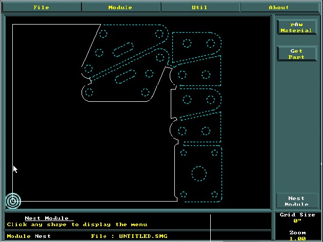
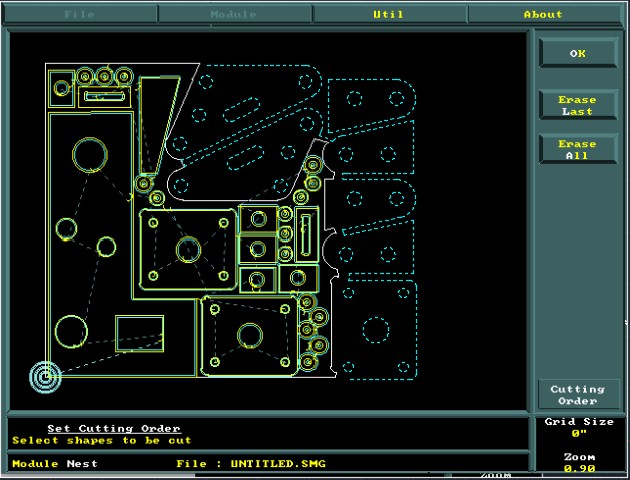
Previous Nesting Leftover Optimization
ServoCAM Software also allows the user to save remaining steel sheets that have not been fully utilized in a previous nest. As you can see in the figure, ServoCAM has taken care to dash the shapes of the parts that is already cut on this scrap in the past, leaving the still usable part blank. This feature is very useful and allows the user to save material by eliminating the loss of steel plate.
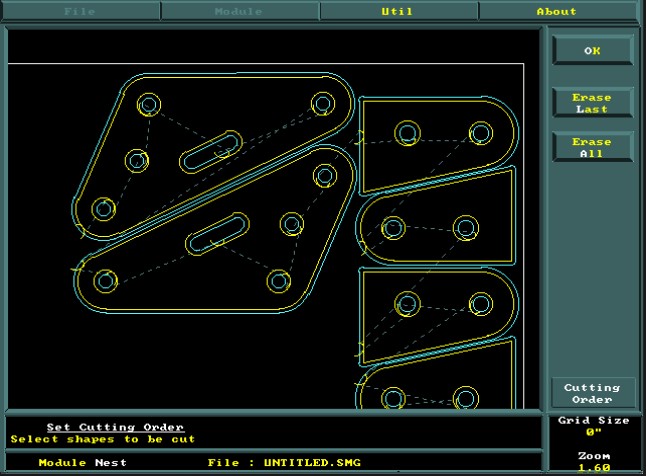
Reload Previous Nesting Leftover Optimization
CAM Software | Nesting on Leftovers
As you can see in this figure, the ServoCAM software allows the user to redo a new nest on previously saved nesting remnants. For this to work the user needs to keep markers to make sure to reposition the leftover to an approximate position like the previous nesting. In this example, the original Zero marker of the previous nesting still appears at the bottom left side of the leftover and must be intact as possible for this to work. The user only has to reposition the remaining on the table and point the torch at the same zero as the previous nest. The new nesting isthen saved in G-code format and send to the CNC Plasma Cutting Machine
CAM Software | Nesting on Leftovers
Inside and Outside Kerf on each parts
The ServoCAM software also allows the user to add and adjust the KERF to a single part or an entire nest. The holes are automatically detected and the KERF will ensure that the process cuts the holes to the correct size. As with the exterior KERF, adjustment will result to the cutting of the the nominal desired value. Whether the parts in the same nest are metric or imperial, by default the KERF adjustment is in inches and will automatically convert to metric dimensions if the part has millimeter dimensions.